Common Installations
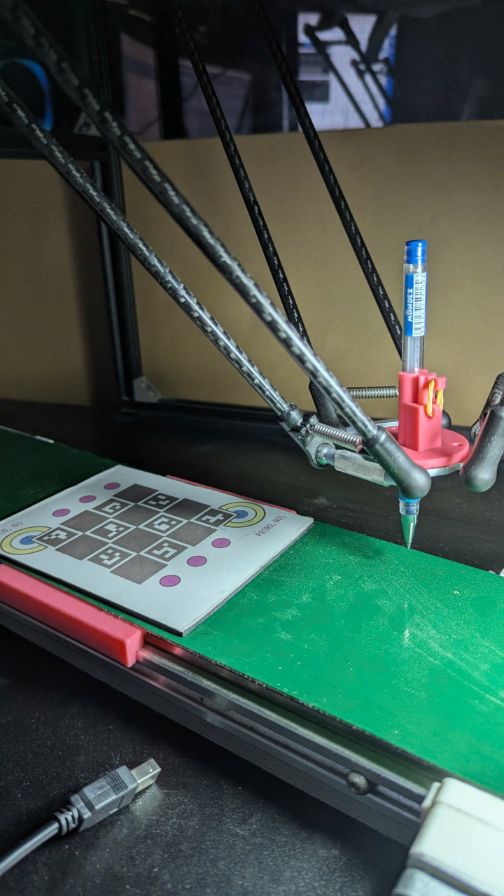
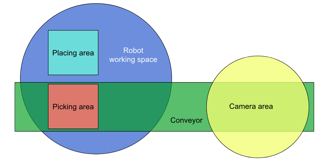
Moving Picking Area and Fixed Placing Area
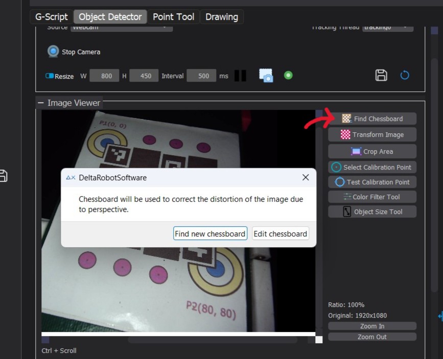
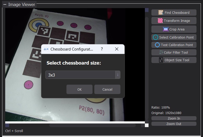
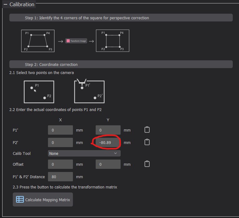
Camera Calibration
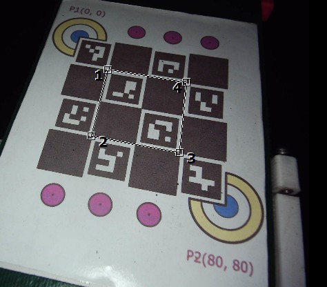
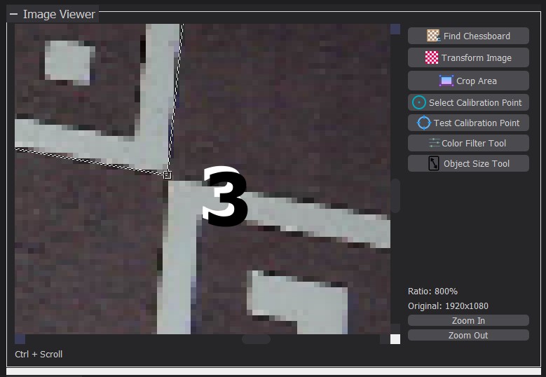
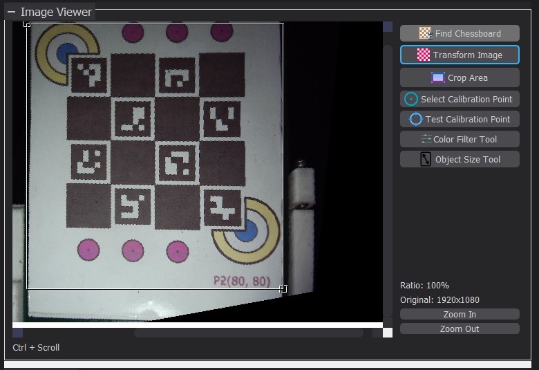
Adjust Perspective
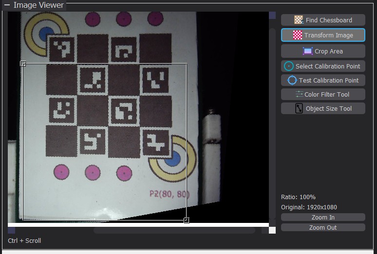
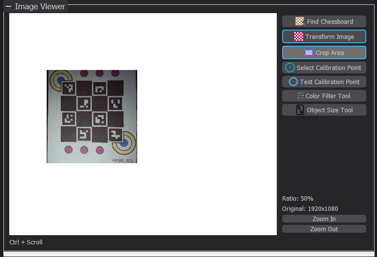
Crop the Working Area
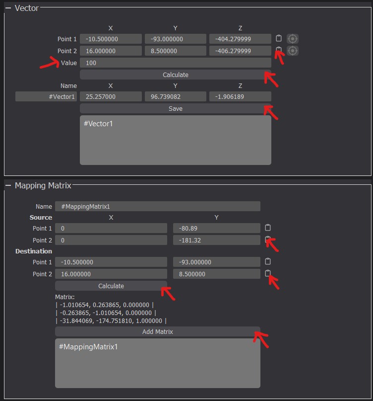
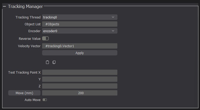
Set up mapping between coordinate systems
From image to conveyor
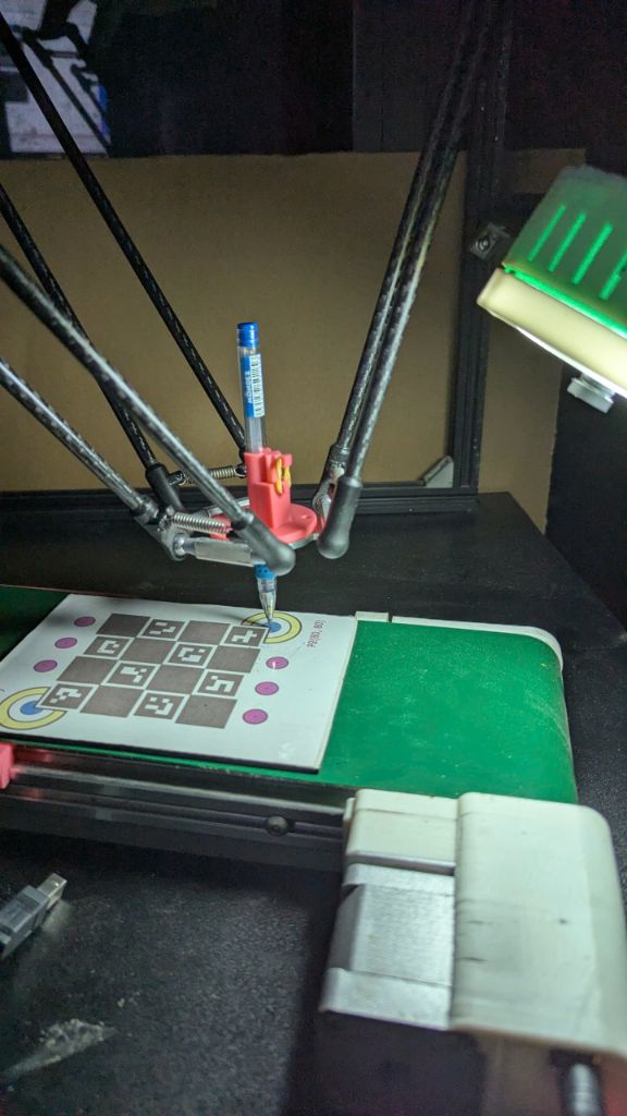
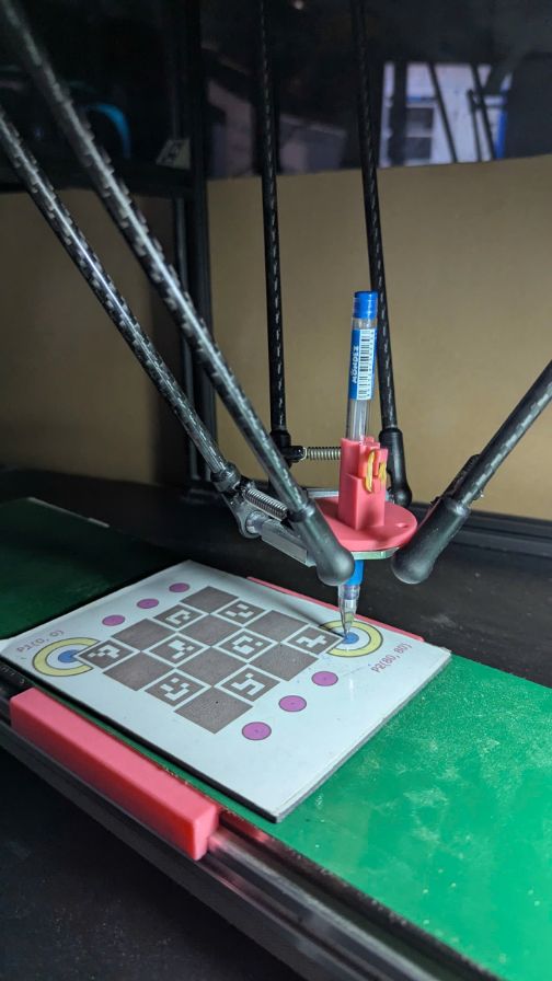
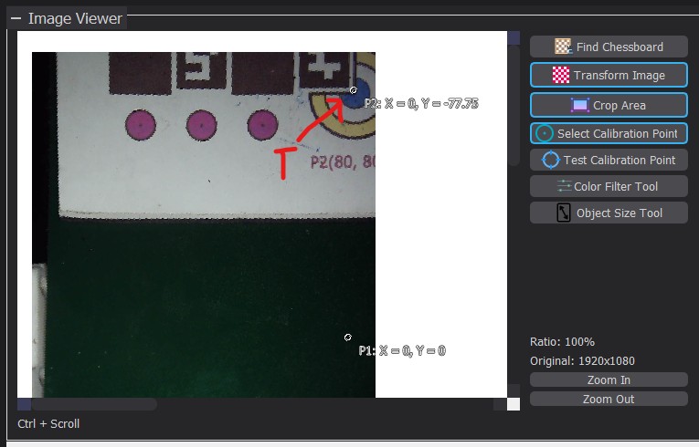
- Select the “Select Calibration Point” tool.
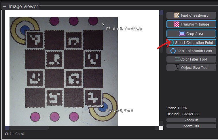
- Click on a marked point on the chessboard, referred to as T.
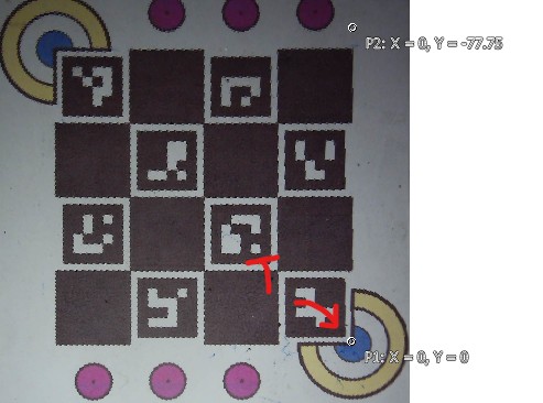
Here, I select the center of the blue circle at the bottom-right corner.
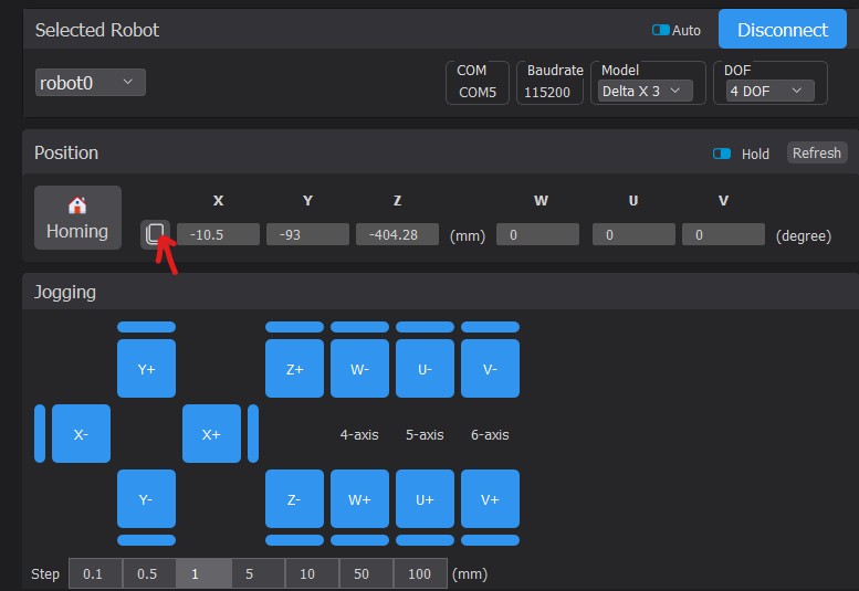
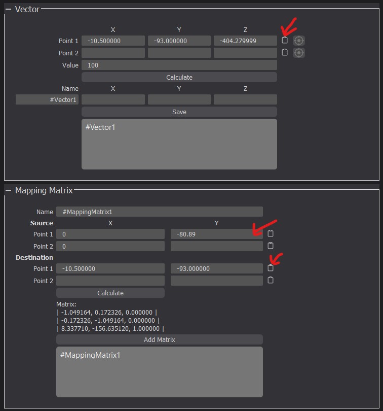
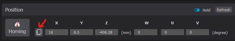
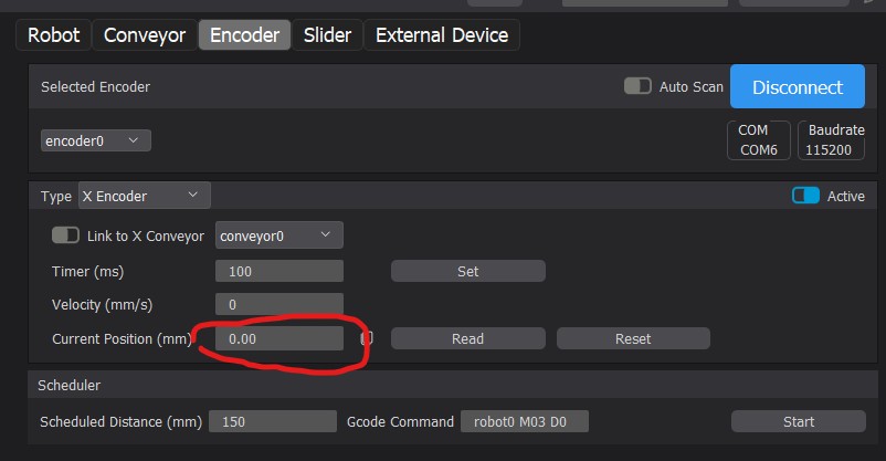
Enter the coordinates of point T on the conveyor here (Calibration → P1').
Set X = 0. If an encoder is used, set Y to the encoder’s value; otherwise, set Y = 0.
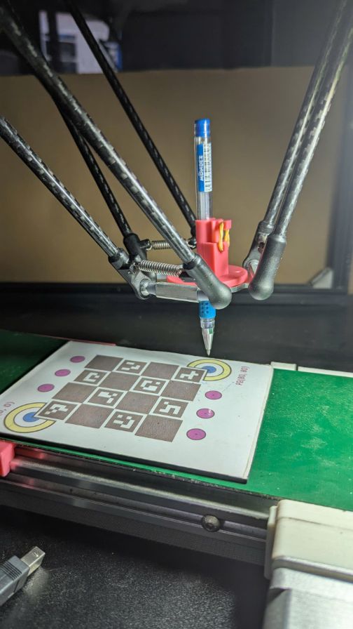
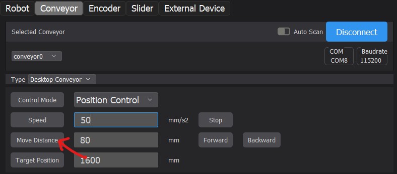
- Move the conveyor by 80 mm.
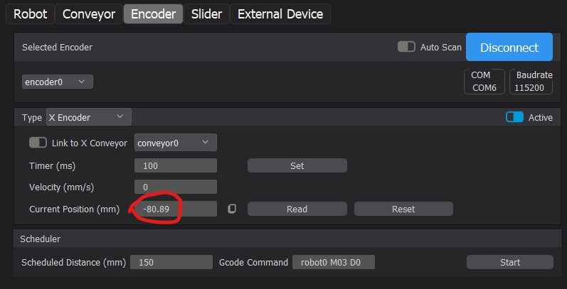
Click on point T again in the image. This time, the coordinates of T are P2'.
Again, set X of P2' = 0, and Y to the encoder’s value or 80 mm.
From conveyor to robot